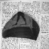
The main research interest at the department lies in the reconstruction of 3D information from images, investigated in projects of archaeological applications. The main goal is to find an automated acquisition method to replace the tiresome task of photographing, measuring and cataloguing of archeological pottery which up to now has been carried out by hand.
Calibration
Camera calibration is used to determine the internal camera geometric and optical characteristics (intrinsic parameters) and the 3D position and orientation of the camera frame relativ to a certain world coordinate system (extrinsic parameters). In this project the two-stage calibration technique introduced from Tsai is used to implement the calibration task. The used calibration pattern consists of 25 white squares which are impressed on the top surface of a black steel block. The corner points of the squares are treated as calibration points. Thus 100 calibration points are used for the calibration task.
Preprocessing Task
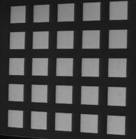
In a first step a threshold is computed by using the histogramm of the intensity image. This threshold is used to produce a binary image. The left picture depicts the intensity image of the calibration grid. The right picture shows the computed binary image.

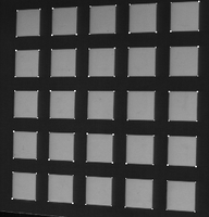
The binary image is now the input for a labeling procedure which assigns the pixels of each detected square with a different number. The labeled image is shown below in the left picture. This labeled image and the intensity image are the input for a procedure which finds the corners of the squares. The labeled image is used to compute start values for the coordinates of the corner points. The intensity image is necessary to compute the corner points in subpixel accuracy. The right picture depicts the image with the detected calibration (corner) points. From these calibration points the corresponding world coordinates are computed.

Calibration Task
The Input of the calibration task are the image coordinates and the corresponding world coordinates of the calibration points, which are computed in the preprocessing step. The intrinsic and extrinsic camera parameters are computed in two steps by using the calculated coordinates.
First stage: Compute 3D Orientation, Position (x and y) and Scale
Second stage: Compute Focal Length, Distortion Coefficients and z Position
Stereo Vision
The search for the correct match of a point is called the correspondence problem and is one of the central and most difficult parts of the stereo problem. Several algorithms were published to compute the disparity between images like the correlation method, the correspondence method, or the phase difference method. If a single point can be located in both stereo images then, given that the relative orientation between the cameras is known, the three dimensional world coordinates may be computed. For a given pair of stereo images and the known orientation parameters of the cameras, the corresponding points are supposed to be on the epipolar lines. Since a parallel camera alignment is used in this project the epipolar lines are the scanlines in both images.
The following equation is used for the matching algorithm: ![]()
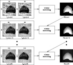
In order to get a dense disparity map and to increase efficiency of the algorithm, 5×5/4 gaussian image pyramids are used to solve the correspondence problem in a hierarchical manner
Fast stereo evaluation is carried out in the top level n (due to low resolution) and yields a disparity map the information of which is considered in the evaluation process of level n-1. Again, the disparity map computed for level n-1 contributes to the stereo evaluation for level n-2 and this process is iterated until the disparity map for the lowest level is computed. If no corresponding point can be found for a candidate in the left image, the information of the pyramid level above is used to get an average disparity information for that point.
Structured Light
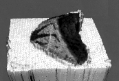
Shape from structured light is based on active triangulation. A very simple technique to achieve depth information with the help of structured light is to scan a scene with a laser plane and to detect the location of the reflected stripe. The depth information can be computed out of the distortion along the detected profile. In order to get dense range information the laser plane has to be moved in the scene. Another technique projects multiple stripes at once onto the scene. In order to distinguish between stripes they are coded (Coded Light Approach) either with different brightness or different colors. In our acquisition system the stripe patterns are generated by a computer controlled transparent Liquid Crystal Display (LCD 640) projector. The light patterns allow the distinction of 2^n projection directions. Each direction can be described uniquely by a n-bit code, which can be seen in Figure (b).
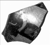
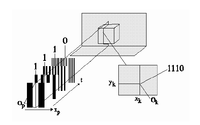
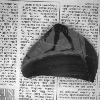
In Figure (a) the intensity image of the test fragment is depicted. This image and one image without illumination is taken prior to the range image computation to determine the maximum and the minimum intensity for each pixel of the fragment. The camera with the optical center O_c is placed at a certain angle to the projector having the optical center at O_p. The camera grabs gray level images I(x,y,t) of the distorted light patterns at different times t, which can be seen in the subsequent figure.
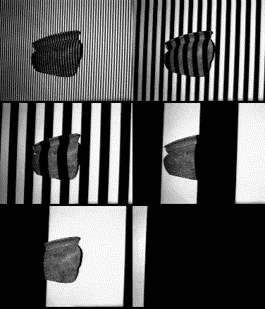
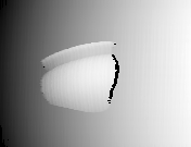
For each pixel in the image a n-bit code is stored. With the help of this code and the known orientation parameters of the acquisition system the 3d-information of the observed scene point can be computed. The orientation parameters are given by a calibration procedure. The robustness of the technique depends on the correct detection of the edge between illuminated and non-illuminated area. Using the calibration parameters the depth information can be computed along the edges. The result is a dense range image. This range image can be taken to construct an object model of the fragment, where the intensity image can be mapped onto the surface in order to produce a realistic model of the surface of the fragment.
With the help of coded light and the known orientation parameters of the acquisition system the 3d-information of the observed scene point can be computed.
Literature
Roger Y. Tsai, “An Efficient and Accurate Camera Calibration Technique for 3d Machine Vision”,Proceedings of IEEE Coonference on Computer Vision and Pattern Recognition,Miami Beach,FL,1986,pp.364-374
R. K. Lenz & R. Y. Tsai, “Techniques for Calibration of the Scale Factor and Image Center for high accuracy 3D Machine Vision Metrology”, IEEE Trans. Pattern Analysis and Machine Intelligence,val PAMI 1, no.5,pp.713-720/87

